MAIN LOGIC MODIFICATIONS FOR THE REVISION-A BOARDSET
Written by Shaun Wood - May 2017
INTRODUCTION
Early versions of the Dragon's Lair main board were a work in progress.
Multiple changes were made during production until approximately serial number 5000, when the design was essentially finalized.
The purpose of this report is to document each change, along with its purpose.
If you have a Revision-A boardset, you should use this document to determine if your board needs any further updates, and if so, make the
needed changes to bring it up to its most stable condition.
Please note that these updates are not absolutely required. If your board is in a working game, then don't mess with it.
However, if your game has a tendency fail at power-up, and often needs to be restarted, then these updates should be performed.
These revisions can also be found on page one of the DL schematics.
PROCEDURE
Remove your board from the machine. Remove the ROM board and remove it from the mounting plate.
Read each section below, and compare the photos to your board. Determine if any individual modification has already been done.
If so, skip to the next mod.
Chances are that you will only find one or two modifications that need to be performed.
(Note - click on any photo to see a larger image.)
Modification 1: R3
Resistor R3 is part of the "beep" audio circuit. It must be 300 ohms.
It was changed from 1K ohm probably to soften the beep sounds. You will find R3 set between U7 and U8.
The color code for 300 ohm is: Orange, Black, Brown, Gold.
The color code for 1K is: Brown, Black, Red, Gold.
Here is a picture of R3 with the proper 300 ohm resistor.
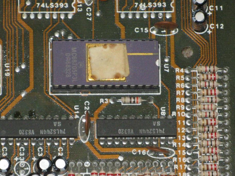
If you have a 1K resistor, change it to a 300 ohm.
Modification 2: The Clock Circuit
The 4Mhz clock signal was a never-ending problem for Cinematronics.They added signal buffers and changed the capacitors multiple times.
For the Rev-C board, they changed it once again.
For this mod, we will be updating to the final version used in the last Rev-A boards.
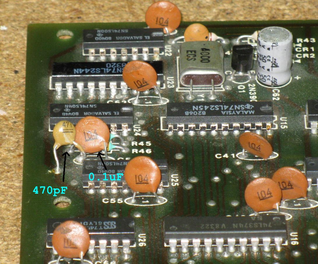
2.1: Capacitors C54 and C63.
C54 should be 0.1uF - look for "104" on the disc.
C63 should be 470pF - look for "471" on the disc - note that C63 has no official location. It is a new addition to the board and is soldered to
one leg of C54 and ground.
2.2: Add a buffer / booster to the 4Mhz signal.
There are two methods for performing this modification. Earlier boards
use a buffer on U17, while later boards use a buffer on U23.
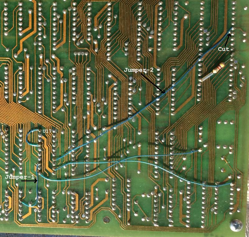
Check to see if your board has U17 installed; if so, examine the
next picture. If jumpers 1 and 2 are present, then the modification is complete. Skip to Modification-3.
If you do not have U17 installed, or the modification is not done, use method 2: U23.
Method 1: U17
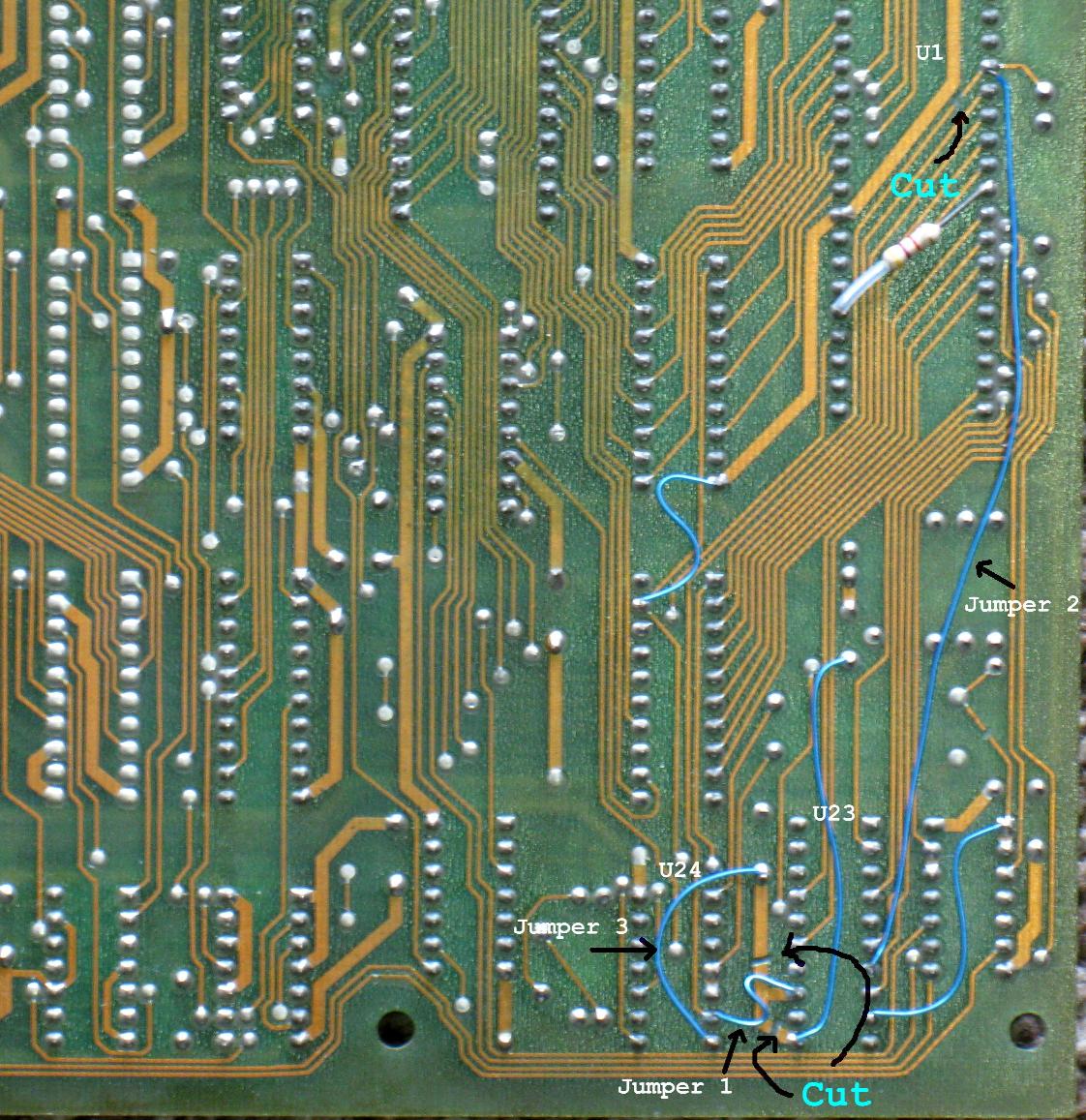
Method 2: U23
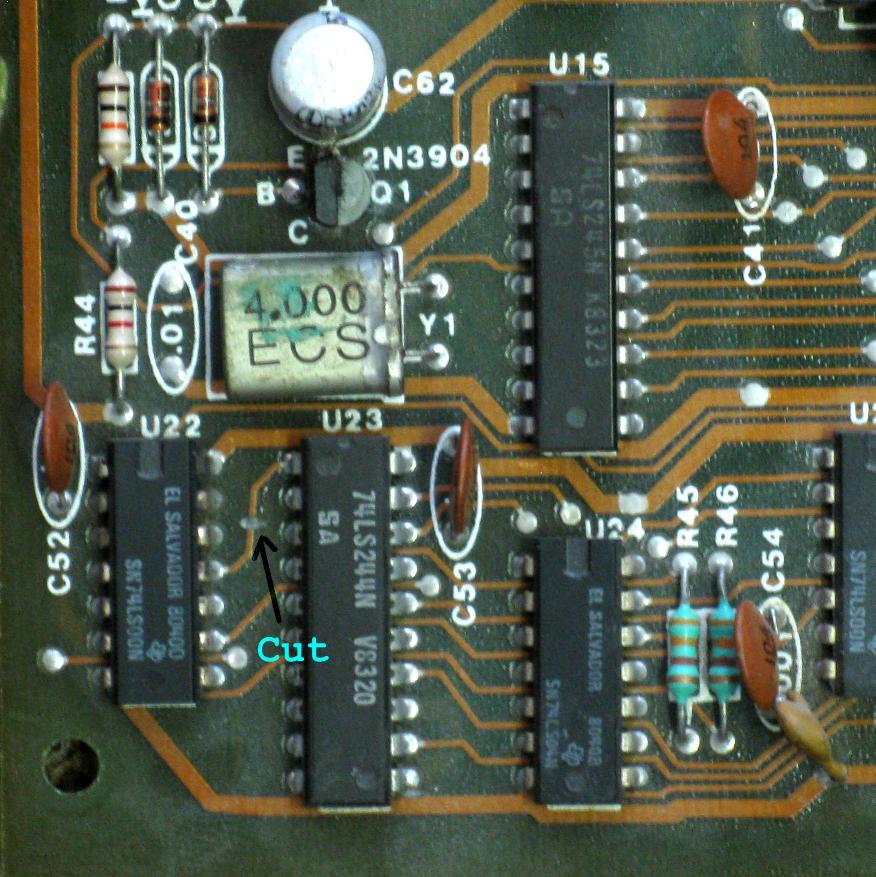
a. Isolate U23:pin-13 by making two cuts
b. Cut the trace at U1:pin-6
c. Add Jumper-1 from U24:pin-6 to U23:pin-13
d. Add Jumper-2 from U23:pin-7 to U1:pin-6
e. Add Jumper-3 from U24:pin-7 to C33
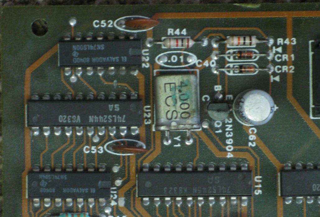
Modification 3: Reset Signal
3.1 - Remove C40 Replace C62
Capacitor C40 is located just above the 4Mhz Crystal.
If it is present, remove it.
Remove and replace the electrolytic capacitor C62 (22uF at 16 volts or
higher). This is not a modification, but it should be done. C62 controls
the duration of the reset pulse, and after 30+ years, it's important to
replace it.
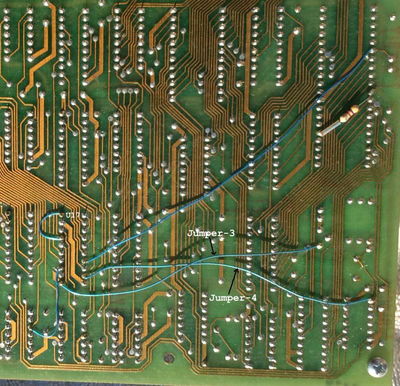
3.2 - Add buffer/driver to Reset signal
Again, for this modification, there are two methods. Earlier boards use a buffer on U17, while later boards use a buffer on U23.
Check to see if your board has U17 installed; if so, examine the next picture. If jumpers 3 and 4 are present, then the modification is complete. Skip to Modification-3.3
If you do not have U17 installed, or the modification is not done, use method 2: U23
Method-1: U17
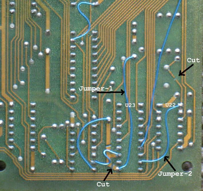
Method-2: U23
Cut the small bit of trace connecting U23:pin-11 to ground.
Make two cuts as shown in the next picture.
Add jumper-1 from the collector of Q1 to U23:pin-11
Add jumper-2 from U23:pin-9 to U22:pin-1
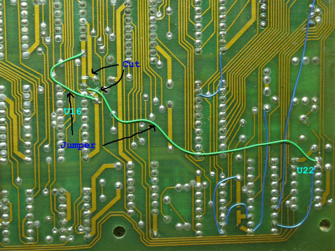
3.3 - Add Reset signal to U16
Isolate U16:pin-1 by making cuts on either side as shown in the next picture.
Add a jumper to re-make the ground line on either side of the cuts.
Add a jumper from U16:pin-1 to U22:pin-1 (or U22:pin-2)
Modification-4: Bus Control
The original design for the Dragon's Lair boardset included a second processing device (U7).
This chip had two purposes:
1. It would provide the "Real Time Clock" needed to keep the game in sync with the laserdisc video.
2. It would act as a security device by monitoring the ROM code and board activity. If anything failed to pass the security inspection, the chip would not produce the RTC signal, and the game would not run.
However, the security features of the chip were never actually put to use in production machines.
The purpose of these modifications is to disable the address and data bus control signals from the unused security part of the processor.
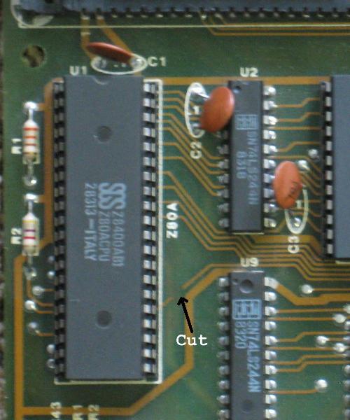
4.1 - Add pull-up resistor to /BUSRQ
Cut the trace as shown in the first photo.
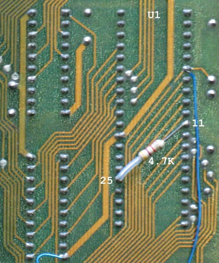
Add a 4.7K ohm resistor from U1:pin-11 to U1:pin-25 as shown in the second photo.
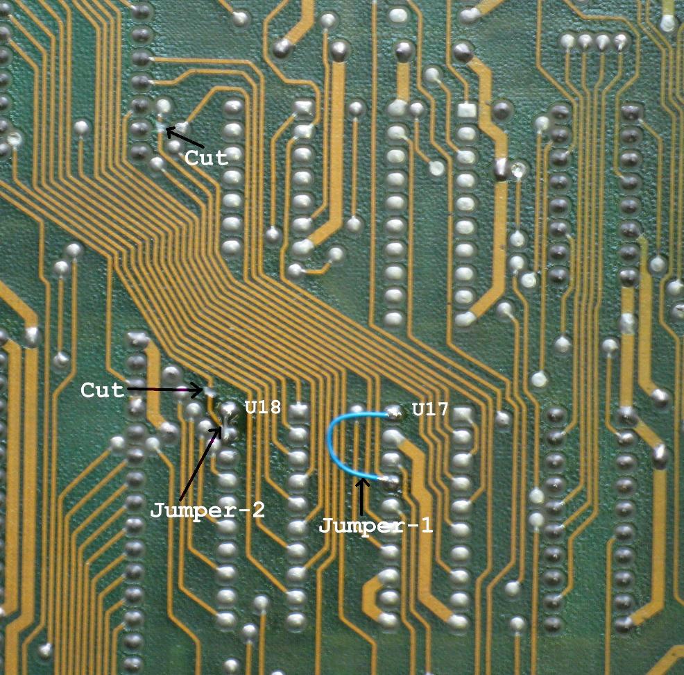
4.2 - Disable port-1 of U17 and disable U18
If your board does not have U17 or U18, then skip ahead to Mod-4.3
Cut the two traces at the locations shown in the next picture.
Add jumper-1 from U17:pin-17 to U17:pin-20
Add jumper-2 from U18:pin-19 to U18:pin-20
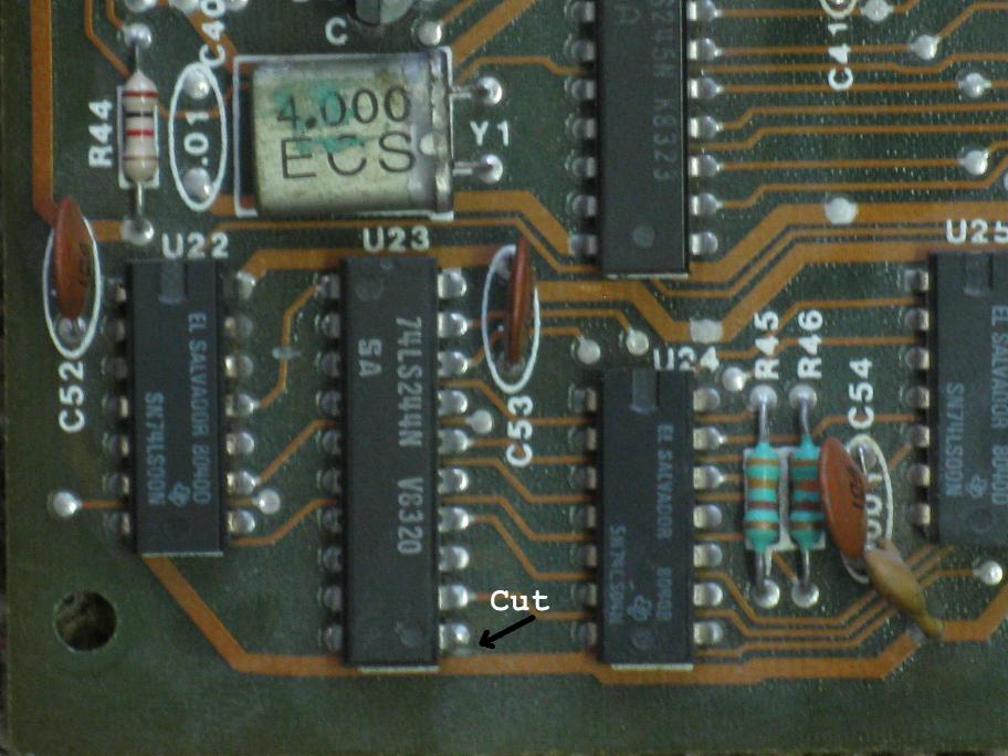
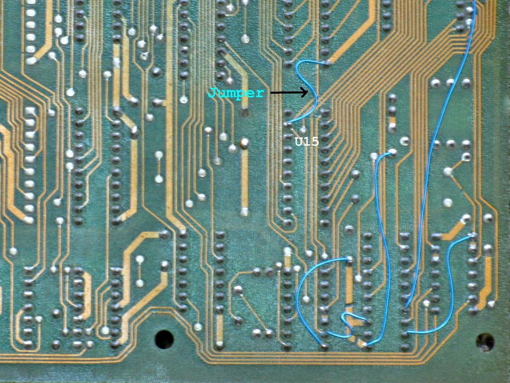
4.3 - Enable Z80A buffers (U2, U9, U15, U23)
Cut the trace between U22 and U23 as shown in the first picture.
Add a jumper from U15:pin-19 to ground as shown in the second picture.
OTHER MODIFICATIONS
These mods are not necissary exept for repair.
LD-V1000 Operation
The Revision-A board is designed to operate the Pioneer PR-7820 laserdisc player, which was the first player model to be used in Dragon's Lair.
Later machines came with the Pioneer LD-V1000 laserdisc player and a Revision-C board to operate it.
The Revision-A board can be modified to operate with the LD-V1000 player.
HOWEVER... In our modern time (2017 at the time of this writing), the Pioneer LD-V1000 is rarely used.
Most Dragon's Lair and Space Ace machines now use some form of replacement player. Common examples are the Dexter player, LaserCon
Merlin, Hi-Tech and LaserAce converters, or use an LD-V8000/4000/2000 ROM set.
These newer players and converters work perfectly with the Revision-A board running in PR-7820 mode.
So, I recommend that you do not do the LD-V1000 modification.
U7 Bypass Modification
The U7 chip (MC68705P5) is used to produce the Real Time Clock (RTC) signal which keeps the game board in sync with the laserdisc video.
This chip has to be programmed before it can be used in the game system, and since the programming has been lost to time, a failed U7 cannot be replaced.
If your Dragon's Lair board fails to boot up. Check the RTC signal at U7:pin-12. You should see a square wave at approximately 30Hz.
If you have no RTC (30Hz) signal, then the 68705 chip is likely dead. Remove it from the board and follow these instructions...
Check that U6 and U13 are installed. If not, install two 74LS393 chips at those locations.
Add a jumper from U6 pin-2 to GND.
Add a jumper from U6 pin-6 to U7 pin-12.
Add a jumper from U13 pin-13 to U19 pin-22.
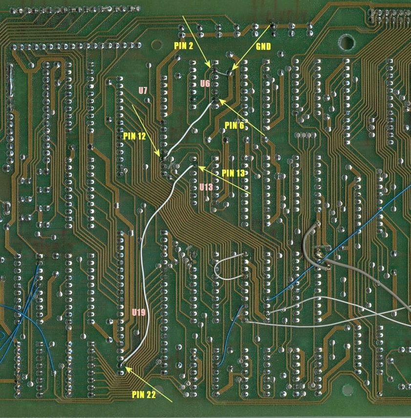
Of course, if your U7 is missing, this modification may have already been done.
Electrolytic Capacitor Replacement
Not a modification, just good policy.
The large capacitors surrounding the harness connector are part of the audio amplifier circuits.
If the ones on your board are original, then they should be replaced.
When they get old, they cause noise on the audio, and they cause the
amplifier chips (U29 and U30) to run hot, which burns them out.
Follow this guide to perform a Dragon's Lair Cap-Kit...
Dragon's Lair Cap-Kit and Audio Fix
Dip Socket Replacement
Again, not a modification, just good policy.
You may want to replace the cheap single-wipe chip sockets with new quality dual-wipe sockets.
U1 and U19 are 40-pin sockets. J1 (player interface connector) and U3 (RAM, if socketed) use 24-pin sockets. The ROM board uses 5 28-pin sockets.
That's it. Enjoy!
DISCLAIMER
The notes above are believed to be correct and work fine for the author. Use at your own risk.