DRAGON'S LAIR / SPACE ACE PCB SOUND VOLUME CONTROL
Written by Shaun Wood - Revised - September 29, 2024
INTRODUCTION
Every move made while playing Dragon's Lair or Space Ace is accompanied by a beep or a buzz. The volume for these sound effects was fixed for noisy arcade environments. Most of these machines are now located in private homes, and the sound level is much louder than necessary. This document will show you step-by-step instructions to add a control to the main board to adjust the volume of the sound effects. Upon completion, you will be able to adjust the volume in a range from 18% to 100% of normal.
PARTS AND TOOLS NEEDED
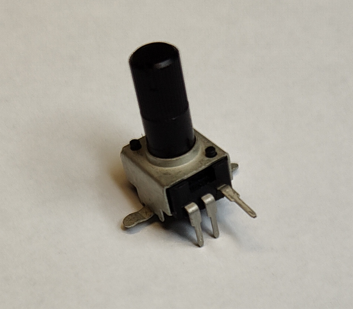
- 1K Potentiometer (I'm using a PTV09A-4020F-B102)
- 3.3K resistor
- 220 ohm resistor
- Soldering Iron
- Solder
- Vacuum de-soldering tool (recommended)
THEORY OF OPERATION
U19 is a General Instruments AY-3-8910 sound chip. Its three independent analog channels are tied together on pins 3, 4 & 38.
This output signal is then controlled by a small network of resistors and capacitors (schematic page 2, grids B3 & B4).
R3 provides impedance matching. C17 bleeds away any high frequency noise. C18 is a DC blocking capacitor.
Resistors R20 and R21 form a voltage divider circuit to provide the fixed volume.
The signal across R21 is passed through C18 to the right amplifier U29.
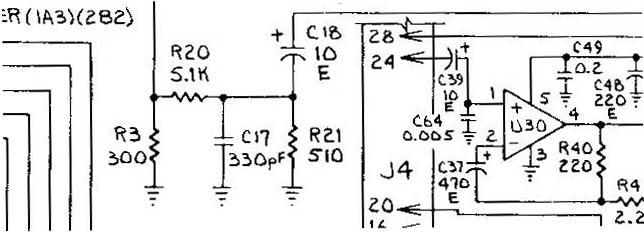
It is the ratio of R21 to the total resistance which determines the volume level.
In the factory setting:
Signal out = Signal in * R21 / ( R21 + R20 ) = Signal in * 510/ (510 + 5100)
Signal out = Signal in * .091
A little more than 9% of the original signal is amplified.
*At this point, if you want to lower the beep volume without all the mess of adding a volume control, you simply need to change R21.
Any resistor of value lower than 510 will work. Suggestions are: 470 or 330 or 220 ohms (lower the number, quieter the beep sound).
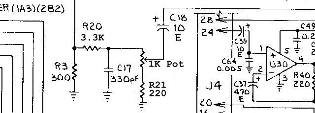
To make the volume adjustable, we need to add a 1K potentiometer, and two resistors.
We will change R20 to 3.3K, and R21 to 220 ohm.
CONSTRUCTION
(Click on the pictures for a larger view.)
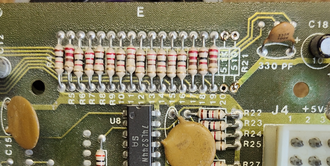
1) Unsolder and remove resistors R20 and R21.
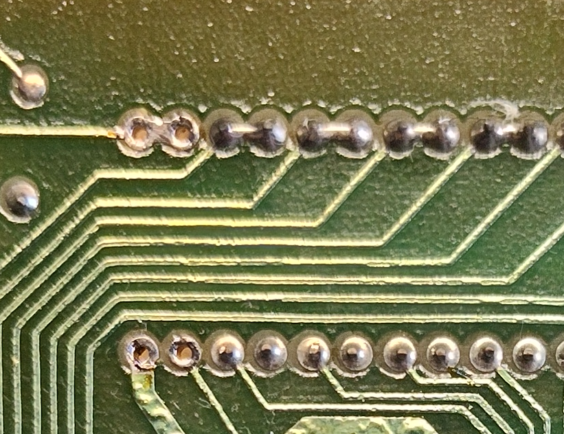
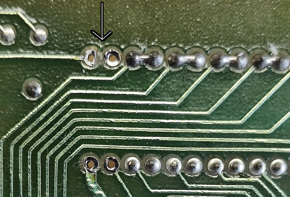
2) From the underside of the board, use a razor blade to cut and remove a small bit of trace to separate the two pins.
3) Bend the legs of the potentiometer, and install as shown...
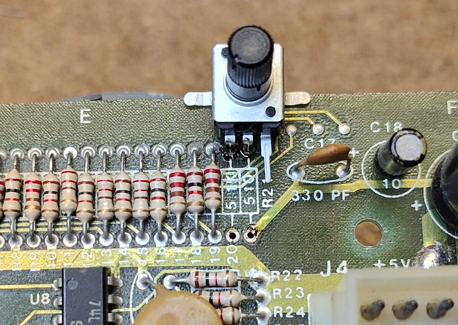
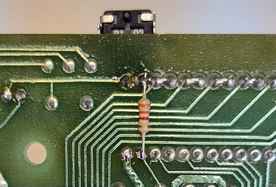
4) Install the new R20 (3.3K) to the bottom of the board, and the new R21 (220) to the top..
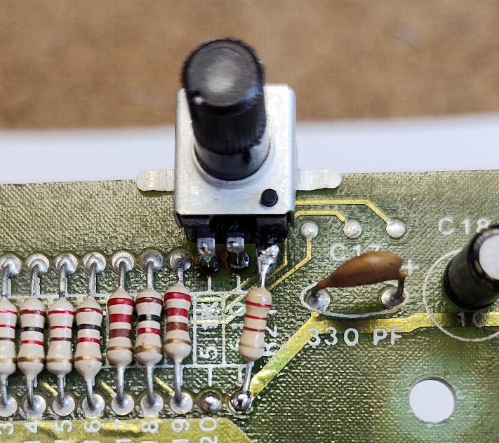
5) Add a touch of hot glue or adhesive or your choice to the mounting wings of the potentiometer and you are all done.
Enjoy!
DISCLAIMER
You are responsible for all work you decide to do on your game. The author of this guide is not responsible if you damage your equipment.
Follow this guide at your own risk.