Remove the 12 capacitors.
(C18, C19, C20, C21, C22, C38, C39, C37, C36, C47, C48, C51)
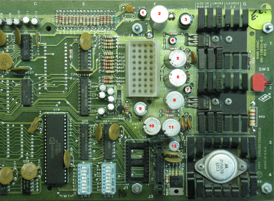
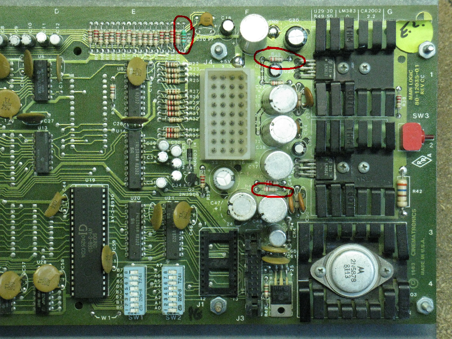
Remove the 3 resistors.
(R21, R36, R41)
AUDIO IMPROVEMENTS FOR DRAGON'S LAIR AND SPACE ACE BOARDSETS
Written by Shaun Wood - January 2021
INTRODUCTION
Dragon's Lair boardsets are notorious for being noisy.
It's especially noticeable during boot-up and the quiet moments when instruction cards are displayed.
There are three primary reasons for this..
The electrolytic capacitors in the audio circuits are old, dried out, and leaking.
The overall amplifier gain is set too high from the factory.
In order to compensate for the excessive amplifier gain, the volume controls are set too low.
PARTS NEEDED
8 - 470uF (35-50V) Capacitors
4 - 10uF (35-50V) Capacitors
2 – 4.7 ohm 1/4W resistors
2 - 1K ohm 1/4W resistors
1 - 22uF (16-50V) capacitor
(note - Only use high quality "name brand" capacitors. Audio-grade preferably)
PROCEDURE
Remove the 12 capacitors.
(C18, C19, C20, C21, C22, C38, C39, C37, C36, C47, C48, C51)
Remove the 3 resistors.
(R21, R36, R41)
INSTALL NEW PARTS
Replace R36 and R41 with 4.7 ohm resistors.
This lowers the amplifier gain from 100X down to 47X.
Replace R21 with a 1K ohm resistor.
This adjusts the beep sound's volume to match the new 47X gain.
(note - Skip this resistor if you have already done the Feedback Volume control modification.)
Replace C18, C21 and C39 with new 10uF capacitors.
Replace C19, C20, C22, C38, C37, C36, C47, and C48 with new 470uF capacitors.
Leave C51 empty and fill the solder holes.
C51 is in parallel with C36. The new 470uF capacitor at C36 replaces both parts.
If you just can't tolerate having a missing capacitor, then fill C51 with a 22uF 50V capacitor.
UNDERSIDE OF BOARD
The Dragon's Lair board combines the sound output from the GI sound chip (beeps) with the laserdisc audio on the right channel.
This second path for audio creates a lower input impedance for the laserdisc audio on the right side, and an imbalance in the volume control settings.
To correct for this we must add a few parts to the left channel input.
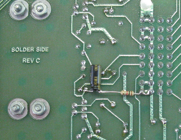
Connect the "+" lead of a 10uF capacitor to the "+" lead of C39 on the underside of the board.
The "-" lead of this new capacitor connects to a 1K resistor, and the other side of the resistor is connected to ground as shown in the picture above.
That's it. Reassemble your board to the mounting plate, and return to the machine.
You will find that proper sound adjustment will now be in the middle range of the volume pots.
My board, connected to a Pioneer LD-V8000 was completely silent after this modification.
However, a note about Dexter...
Dexter uses a Raspberry Pi to deliver audio to the game. Unfortunately, the Raspberry Pi is not designed for hi-fidelity audio.
Even after this modification, there will still be some buzz/hum coming from the Dexter player, but it will be much quieter than it was.
Enjoy!
THE RESET CAPACITOR
Replace the capacitor at C62 with the remaining 22uF cap.
This capacitor is part of the bootup reset circuit, and although it's not part of the audio circuit we have been working on,
it's very important to board stability. So let's go ahead and replace it.
Sorry I don't have a picture.
DISCLAIMER OF LIABILITY
The author makes no warranty or assumes any legal liability or responsibility for the accuracy, completeness, or usefulness of any information, apparatus, product, or process in this document.
Use at your own risk.